
You maintain
can follow the steps for the step.
Always select the exact model before you start. The guides include maintenance of existing equipment. New locations, cableling and enrollment can require your own design and engineering work.
Customer / facility: [fill in]
Service Contact / agreed test method: [fill in]
In case of smoke, fire or other real danger, the event should be handled first. Do not use the maintenance procedure to cause an active hazard alarm to disappear.
Preparation and final control
Before you start
- Check the product code and full model on the label. Photograph its orientation, mount and battery compartment before changing anything.
- Arrange maintenance and testing with the monitoring station or service provider where applicable. Normal disarming does not necessarily disable tamper, fire or panic alarms. Have any service mode confirmed before opening equipment.
- Work on one device at a time with safe, stable access. A removed or unpowered sensor does not protect its area. Restore protection before finishing.
Batteries and small parts
- Use the exact specified type, voltage and number. Follow the polarity markings. Replace the complete set together; do not mix old and new cells or different chemistries.
- Do not recharge disposable batteries, short the terminals or bridge both terminals with a metal tool. Keep coin cells and small parts away from children. Stop if a battery leaks, heats up or is damaged.
- Take used batteries to a battery collection point. Do not reset the sensor, remove it from the app or change switches as part of ordinary battery replacement.
Finished when these checks are complete
- The cover and mount are fitted correctly. No cable is trapped. The sensor retains its previous position, orientation and coverage.
- The panel shows normal communication, battery and tamper status after the appropriate startup and test. A light on the sensor alone does not confirm that alarm reporting works.
- The agreed functions are tested, receipt is confirmed where applicable, and service/test mode has ended. Record the date, battery type and result. For an unresolved fault, contact service and explain that protection may be reduced.
General maintenance advice. The product's specific manual and the agreed procedures of the plant go ahead.
Finn artikkelen
Finn artikkelen
Finn artikkelen
Aluminum junction box PFA137 Black
Coverage: Use and checks – mounting details missing

Manual for this product
Battery/power: Passive camera fastener/connector box; no battery switch procedure
A connecting box can contain connections even if the box itself does not have a battery.
1. Take down or open
- Do not undo a load-bearing camera mount without supporting the camera and understanding the cable routing.
4. Test and confirm normal operation
- After the work, check that the mounting is secure, the field of view is correct and the cable entries are protected.
Attach and Mount
- Check that the mount, screws and visible cable entries are secure and undamaged.
- The source is a product sheet, not a complete removal, sealing and refitting procedure. Use the mounting drawing for this exact mount.
Original images and technical drawings
Technical drawing is not installed here yet. Open the associated original manual and control model before demounting.
Check that the drawing and any variations in the original manual are consistent with the device. Sources checked 08.09.2026. The step marked as derived is not an explicit disunity instruction from the manufacturer.
Aluminum junction box PFA137
Coverage: Use and checks – mounting details missing

Manual for this product
Battery/power: Passive camera fastener/connector box; no battery switch procedure
A connecting box can contain connections even if the box itself does not have a battery.
1. Take down or open
- Do not undo a load-bearing camera mount without supporting the camera and understanding the cable routing.
4. Test and confirm normal operation
- After the work, check that the mounting is secure, the field of view is correct and the cable entries are protected.
Attach and Mount
- Check that the mount, screws and visible cable entries are secure and undamaged.
- The source is a product sheet, not a complete removal, sealing and refitting procedure. Use the mounting drawing for this exact mount.
Original images and technical drawings
Technical drawing is not installed here yet. Open the associated original manual and control model before demounting.
Check that the drawing and any variations in the original manual are consistent with the device. Sources checked 08.09.2026. The step marked as derived is not an explicit disunity instruction from the manufacturer.
VESTA wall mounting bracket
Coverage: Use and checks – mounting details missing

Manual for this product
Battery/power: Passive camera fastener/connector box; no battery switch procedure
A connecting box can contain connections even if the box itself does not have a battery.
1. Take down or open
- Do not undo a load-bearing camera mount without supporting the camera and understanding the cable routing.
4. Test and confirm normal operation
- After the work, check that the mounting is secure, the field of view is correct and the cable entries are protected.
Attach and Mount
- Check that the mount, screws and visible cable entries are secure and undamaged.
- The source is a product sheet, not a complete removal, sealing and refitting procedure. Use the mounting drawing for this exact mount.
Original images and technical drawings
Technical drawing is not installed here yet. Open the associated original manual and control model before demounting.
Check that the drawing and any variations in the original manual are consistent with the device. Sources checked 08.09.2026. The step marked as derived is not an explicit disunity instruction from the manufacturer.
PFA-152-E / Stolpefeste
Coverage: Use and checks – mounting details missing

Manual for this product
Battery/power: Passive camera fastener/connector box; no battery switch procedure
A connecting box can contain connections even if the box itself does not have a battery.
1. Take down or open
- Do not undo a load-bearing camera mount without supporting the camera and understanding the cable routing.
4. Test and confirm normal operation
- After the work, check that the mounting is secure, the field of view is correct and the cable entries are protected.
Attach and Mount
- Check that the mount, screws and visible cable entries are secure and undamaged.
- The source is a product sheet, not a complete removal, sealing and refitting procedure. Use the mounting drawing for this exact mount.
Original images and technical drawings
Technical drawing is not installed here yet. Open the associated original manual and control model before demounting.
Check that the drawing and any variations in the original manual are consistent with the device. Sources checked 08.09.2026. The step marked as derived is not an explicit disunity instruction from the manufacturer.
VESTA svart utendørs koblingsboks
Coverage: Use and checks – mounting details missing

Manual for this product
Battery/power: Passive camera fastener/connector box; no battery switch procedure
A connecting box can contain connections even if the box itself does not have a battery.
1. Take down or open
- Do not undo a load-bearing camera mount without supporting the camera and understanding the cable routing.
4. Test and confirm normal operation
- After the work, check that the mounting is secure, the field of view is correct and the cable entries are protected.
Attach and Mount
- Check that the mount, screws and visible cable entries are secure and undamaged.
- The source is a product sheet, not a complete removal, sealing and refitting procedure. Use the mounting drawing for this exact mount.
Original images and technical drawings
Technical drawing is not installed here yet. Open the associated original manual and control model before demounting.
Check that the drawing and any variations in the original manual are consistent with the device. Sources checked 08.09.2026. The step marked as derived is not an explicit disunity instruction from the manufacturer.
VESTA outdoor junction box
Coverage: Use and checks – mounting details missing

Manual for this product
Battery/power: Passive camera fastener/connector box; no battery switch procedure
A connecting box can contain connections even if the box itself does not have a battery.
1. Take down or open
- Do not undo a load-bearing camera mount without supporting the camera and understanding the cable routing.
4. Test and confirm normal operation
- After the work, check that the mounting is secure, the field of view is correct and the cable entries are protected.
Attach and Mount
- Check that the mount, screws and visible cable entries are secure and undamaged.
- The source is a product sheet, not a complete removal, sealing and refitting procedure. Use the mounting drawing for this exact mount.
Original images and technical drawings
Technical drawing is not installed here yet. Open the associated original manual and control model before demounting.
Check that the drawing and any variations in the original manual are consistent with the device. Sources checked 08.09.2026. The step marked as derived is not an explicit disunity instruction from the manufacturer.
VESTA pole mounting bracket
Coverage: Use and checks – mounting details missing

Manual for this product
Battery/power: Passive camera fastener/connector box; no battery switch procedure
A connecting box can contain connections even if the box itself does not have a battery.
1. Take down or open
- Do not undo a load-bearing camera mount without supporting the camera and understanding the cable routing.
4. Test and confirm normal operation
- After the work, check that the mounting is secure, the field of view is correct and the cable entries are protected.
Attach and Mount
- Check that the mount, screws and visible cable entries are secure and undamaged.
- The source is a product sheet, not a complete removal, sealing and refitting procedure. Use the mounting drawing for this exact mount.
Original images and technical drawings
Technical drawing is not installed here yet. Open the associated original manual and control model before demounting.
Check that the drawing and any variations in the original manual are consistent with the device. Sources checked 08.09.2026. The step marked as derived is not an explicit disunity instruction from the manufacturer.
VESTA aluminum wall bracket
Coverage: Use and checks – mounting details missing

Manual for this product
Battery/power: Passive camera fastener/connector box; no battery switch procedure
A connecting box can contain connections even if the box itself does not have a battery.
1. Take down or open
- Do not undo a load-bearing camera mount without supporting the camera and understanding the cable routing.
4. Test and confirm normal operation
- After the work, check that the mounting is secure, the field of view is correct and the cable entries are protected.
Attach and Mount
- Check that the mount, screws and visible cable entries are secure and undamaged.
- The source is a product sheet, not a complete removal, sealing and refitting procedure. Use the mounting drawing for this exact mount.
Original images and technical drawings
Technical drawing is not installed here yet. Open the associated original manual and control model before demounting.
Check that the drawing and any variations in the original manual are consistent with the device. Sources checked 08.09.2026. The step marked as derived is not an explicit disunity instruction from the manufacturer.
Aluminum junction box
Coverage: Use and checks – mounting details missing

Manual for this product
Battery/power: Passive camera fastener/connector box; no battery switch procedure
A connecting box can contain connections even if the box itself does not have a battery.
1. Take down or open
- Do not undo a load-bearing camera mount without supporting the camera and understanding the cable routing.
4. Test and confirm normal operation
- After the work, check that the mounting is secure, the field of view is correct and the cable entries are protected.
Attach and Mount
- Check that the mount, screws and visible cable entries are secure and undamaged.
- The source is a product sheet, not a complete removal, sealing and refitting procedure. Use the mounting drawing for this exact mount.
Original images and technical drawings
Technical drawing is not installed here yet. Open the associated original manual and control model before demounting.
Check that the drawing and any variations in the original manual are consistent with the device. Sources checked 08.09.2026. The step marked as derived is not an explicit disunity instruction from the manufacturer.
Aluminum junction box
Coverage: Use and checks – mounting details missing

Manual for this product
Battery/power: Passive camera fastener/connector box; no battery switch procedure
A connecting box can contain connections even if the box itself does not have a battery.
1. Take down or open
- Do not undo a load-bearing camera mount without supporting the camera and understanding the cable routing.
4. Test and confirm normal operation
- After the work, check that the mounting is secure, the field of view is correct and the cable entries are protected.
Attach and Mount
- Check that the mount, screws and visible cable entries are secure and undamaged.
- The source is a product sheet, not a complete removal, sealing and refitting procedure. Use the mounting drawing for this exact mount.
Original images and technical drawings
Technical drawing is not installed here yet. Open the associated original manual and control model before demounting.
Check that the drawing and any variations in the original manual are consistent with the device. Sources checked 08.09.2026. The step marked as derived is not an explicit disunity instruction from the manufacturer.
Vesta utendørs 4MP 2,8mm bullet
Coverage: Use and checks – removal manual missing

Manual for this product
Battery / Power: No customer exchange procedure for battery documented in this product sheet
Detailed opening, sealing, any memory card access and cable require the model installation manual. No generic cover direction is used.
1. Take down or open
- Leave the camera on its mount. The source does not explain how to release this housing or bracket.
4. Test and confirm normal operation
- Open the camera's live view in the agreed application. Confirm that it shows the correct location and updates.
- If recording is included: check a recent recording and its timestamp. Live view alone does not confirm recording.
- Note which functions fail and give the product code to support.
Attach and Mount
- Check externally that the mount and cables are intact and the lens has a clear view. Do not force the lens or moving head.
Original images and technical drawings
Technical drawing is not installed here yet. Open the associated original manual and control model before demounting.
Check that the drawing and any variations in the original manual are consistent with the device. Sources checked 08.09.2026. The step marked as derived is not an explicit disunity instruction from the manufacturer.
Vesta utendørs 4MP 2,8mm vandalsikker dome
Coverage: Use and checks – removal manual missing

Manual for this product
Battery / Power: No customer exchange procedure for battery documented in this product sheet
Detailed opening, sealing, any memory card access and cable require the model installation manual. No generic cover direction is used.
1. Take down or open
- Leave the camera on its mount. The source does not explain how to release this housing or bracket.
4. Test and confirm normal operation
- Open the camera's live view in the agreed application. Confirm that it shows the correct location and updates.
- If recording is included: check a recent recording and its timestamp. Live view alone does not confirm recording.
- Note which functions fail and give the product code to support.
Attach and Mount
- Check externally that the mount and cables are intact and the lens has a clear view. Do not force the lens or moving head.
Original images and technical drawings
Technical drawing is not installed here yet. Open the associated original manual and control model before demounting.
Check that the drawing and any variations in the original manual are consistent with the device. Sources checked 08.09.2026. The step marked as derived is not an explicit disunity instruction from the manufacturer.
Vesta utendørs 4MP 2,8mm vandalsikker dome
Coverage: Use and checks – removal manual missing

Manual for this product
Battery / Power: No customer exchange procedure for battery documented in this product sheet
Detailed opening, sealing, any memory card access and cable require the model installation manual. No generic cover direction is used.
1. Take down or open
- Leave the camera on its mount. The source does not explain how to release this housing or bracket.
4. Test and confirm normal operation
- Open the camera's live view in the agreed application. Confirm that it shows the correct location and updates.
- If recording is included: check a recent recording and its timestamp. Live view alone does not confirm recording.
- Note which functions fail and give the product code to support.
Attach and Mount
- Check externally that the mount and cables are intact and the lens has a clear view. Do not force the lens or moving head.
Original images and technical drawings
Technical drawing is not installed here yet. Open the associated original manual and control model before demounting.
Check that the drawing and any variations in the original manual are consistent with the device. Sources checked 08.09.2026. The step marked as derived is not an explicit disunity instruction from the manufacturer.
Vesta utendørs 4MP 2,8mm bullet sort
Coverage: Use and checks – removal manual missing

Manual for this product
Battery / Power: No customer exchange procedure for battery documented in this product sheet
Detailed opening, sealing, any memory card access and cable require the model installation manual. No generic cover direction is used.
1. Take down or open
- Leave the camera on its mount. The source does not explain how to release this housing or bracket.
4. Test and confirm normal operation
- Open the camera's live view in the agreed application. Confirm that it shows the correct location and updates.
- If recording is included: check a recent recording and its timestamp. Live view alone does not confirm recording.
- Note which functions fail and give the product code to support.
Attach and Mount
- Check externally that the mount and cables are intact and the lens has a clear view. Do not force the lens or moving head.
Original images and technical drawings
Technical drawing is not installed here yet. Open the associated original manual and control model before demounting.
Check that the drawing and any variations in the original manual are consistent with the device. Sources checked 08.09.2026. The step marked as derived is not an explicit disunity instruction from the manufacturer.
Vesta Entry Serie 10-kanals IP NVR med 8 PoE
Coverage: Use and checks – internal work requires service

Manual for this product
Battery/power: No documented customer exchange procedure for internal batteries
Moving, power disconnection and disk replacement can stop recording. The product sheet does not provide a full procedure for safe termination and demounting.
1. Take down or open
- Do not open the recorder or remove drives to investigate a warning.
4. Test and confirm normal operation
- Check that the agreed cameras show an updated live view.
- Play a recent recording from each relevant channel. Check the date, time and recording period.
- For drive, network or power faults: note the message and arrange service.
Attach and Mount
- Keep ventilation openings clear. Check visible cable connections without unplugging them during recording.
Original images and technical drawings
Technical drawing is not installed here yet. Open the associated original manual and control model before demounting.
Check that the drawing and any variations in the original manual are consistent with the device. Sources checked 08.09.2026. The step marked as derived is not an explicit disunity instruction from the manufacturer.
Vesta utendørs 4MP 2,8mm vandalsikker Turret
Coverage: Use and checks – removal manual missing

Manual for this product
Battery / Power: No customer exchange procedure for battery documented in this product sheet
Detailed opening, sealing, any memory card access and cable require the model installation manual. No generic cover direction is used.
1. Take down or open
- Leave the camera on its mount. The source does not explain how to release this housing or bracket.
4. Test and confirm normal operation
- Open the camera's live view in the agreed application. Confirm that it shows the correct location and updates.
- If recording is included: check a recent recording and its timestamp. Live view alone does not confirm recording.
- Note which functions fail and give the product code to support.
Attach and Mount
- Check externally that the mount and cables are intact and the lens has a clear view. Do not force the lens or moving head.
Original images and technical drawings
Technical drawing is not installed here yet. Open the associated original manual and control model before demounting.
Check that the drawing and any variations in the original manual are consistent with the device. Sources checked 08.09.2026. The step marked as derived is not an explicit disunity instruction from the manufacturer.
Vesta utendørs 6MP 2,8mm vandalsikker Turret
Coverage: Use and checks – removal manual missing
Manual for this product
Battery / Power: No customer exchange procedure for battery documented in this product sheet
Detailed opening, sealing, any memory card access and cable require the model installation manual. No generic cover direction is used.
1. Take down or open
- Leave the camera on its mount. The source does not explain how to release this housing or bracket.
4. Test and confirm normal operation
- Open the camera's live view in the agreed application. Confirm that it shows the correct location and updates.
- If recording is included: check a recent recording and its timestamp. Live view alone does not confirm recording.
- Note which functions fail and give the product code to support.
Attach and Mount
- Check externally that the mount and cables are intact and the lens has a clear view. Do not force the lens or moving head.
Original images and technical drawings
Technical drawing is not installed here yet. Open the associated original manual and control model before demounting.
Check that the drawing and any variations in the original manual are consistent with the device. Sources checked 08.09.2026. The step marked as derived is not an explicit disunity instruction from the manufacturer.
Vesta utendørs 5MP 2,8mm bullet
Coverage: Use and checks – removal manual missing

Manual for this product
Battery / Power: No customer exchange procedure for battery documented in this product sheet
Detailed opening, sealing, any memory card access and cable require the model installation manual. No generic cover direction is used.
1. Take down or open
- Leave the camera on its mount. The source does not explain how to release this housing or bracket.
4. Test and confirm normal operation
- Open the camera's live view in the agreed application. Confirm that it shows the correct location and updates.
- If recording is included: check a recent recording and its timestamp. Live view alone does not confirm recording.
- Note which functions fail and give the product code to support.
Attach and Mount
- Check externally that the mount and cables are intact and the lens has a clear view. Do not force the lens or moving head.
Original images and technical drawings
Technical drawing is not installed here yet. Open the associated original manual and control model before demounting.
Check that the drawing and any variations in the original manual are consistent with the device. Sources checked 08.09.2026. The step marked as derived is not an explicit disunity instruction from the manufacturer.
Vesta 16-kanals Entry Serie IP NVR med 8 PoE
Coverage: Use and checks – internal work requires service
Manual for this product
Battery/power: No documented customer exchange procedure for internal batteries
Moving, power disconnection and disk replacement can stop recording. The product sheet does not provide a full procedure for safe termination and demounting.
1. Take down or open
- Do not open the recorder or remove drives to investigate a warning.
4. Test and confirm normal operation
- Check that the agreed cameras show an updated live view.
- Play a recent recording from each relevant channel. Check the date, time and recording period.
- For drive, network or power faults: note the message and arrange service.
Attach and Mount
- Keep ventilation openings clear. Check visible cable connections without unplugging them during recording.
Original images and technical drawings
Technical drawing is not installed here yet. Open the associated original manual and control model before demounting.
Check that the drawing and any variations in the original manual are consistent with the device. Sources checked 08.09.2026. The step marked as derived is not an explicit disunity instruction from the manufacturer.
Vesta utendørs 4MP 2,8mm vandalsikker Turret
Coverage: Use and checks – removal manual missing
Manual for this product
Battery / Power: No customer exchange procedure for battery documented in this product sheet
Detailed opening, sealing, any memory card access and cable require the model installation manual. No generic cover direction is used.
1. Take down or open
- Leave the camera on its mount. The source does not explain how to release this housing or bracket.
4. Test and confirm normal operation
- Open the camera's live view in the agreed application. Confirm that it shows the correct location and updates.
- If recording is included: check a recent recording and its timestamp. Live view alone does not confirm recording.
- Note which functions fail and give the product code to support.
Attach and Mount
- Check externally that the mount and cables are intact and the lens has a clear view. Do not force the lens or moving head.
Original images and technical drawings
Technical drawing is not installed here yet. Open the associated original manual and control model before demounting.
Check that the drawing and any variations in the original manual are consistent with the device. Sources checked 08.09.2026. The step marked as derived is not an explicit disunity instruction from the manufacturer.
Vesta utendørs 4MP 2,8mm bullet
Coverage: Use and checks – removal manual missing
Manual for this product
Battery / Power: No customer exchange procedure for battery documented in this product sheet
Detailed opening, sealing, any memory card access and cable require the model installation manual. No generic cover direction is used.
1. Take down or open
- Leave the camera on its mount. The source does not explain how to release this housing or bracket.
4. Test and confirm normal operation
- Open the camera's live view in the agreed application. Confirm that it shows the correct location and updates.
- If recording is included: check a recent recording and its timestamp. Live view alone does not confirm recording.
- Note which functions fail and give the product code to support.
Attach and Mount
- Check externally that the mount and cables are intact and the lens has a clear view. Do not force the lens or moving head.
Original images and technical drawings
Technical drawing is not installed here yet. Open the associated original manual and control model before demounting.
Check that the drawing and any variations in the original manual are consistent with the device. Sources checked 08.09.2026. The step marked as derived is not an explicit disunity instruction from the manufacturer.
Vesta utendørs 4MP 2,7-13.5mm vandalsikker dome
Coverage: Use and checks – removal manual missing

Manual for this product
Battery / Power: No customer exchange procedure for battery documented in this product sheet
Detailed opening, sealing, any memory card access and cable require the model installation manual. No generic cover direction is used.
1. Take down or open
- Leave the camera on its mount. The source does not explain how to release this housing or bracket.
4. Test and confirm normal operation
- Open the camera's live view in the agreed application. Confirm that it shows the correct location and updates.
- If recording is included: check a recent recording and its timestamp. Live view alone does not confirm recording.
- Note which functions fail and give the product code to support.
Attach and Mount
- Check externally that the mount and cables are intact and the lens has a clear view. Do not force the lens or moving head.
Original images and technical drawings
Technical drawing is not installed here yet. Open the associated original manual and control model before demounting.
Check that the drawing and any variations in the original manual are consistent with the device. Sources checked 08.09.2026. The step marked as derived is not an explicit disunity instruction from the manufacturer.
Vesta utendørs 4MP 2,7-13.5mm vandalsikker dome Sort
Coverage: Use and checks – removal manual missing

Manual for this product
Battery / Power: No customer exchange procedure for battery documented in this product sheet
Detailed opening, sealing, any memory card access and cable require the model installation manual. No generic cover direction is used.
1. Take down or open
- Leave the camera on its mount. The source does not explain how to release this housing or bracket.
4. Test and confirm normal operation
- Open the camera's live view in the agreed application. Confirm that it shows the correct location and updates.
- If recording is included: check a recent recording and its timestamp. Live view alone does not confirm recording.
- Note which functions fail and give the product code to support.
Attach and Mount
- Check externally that the mount and cables are intact and the lens has a clear view. Do not force the lens or moving head.
Original images and technical drawings
Technical drawing is not installed here yet. Open the associated original manual and control model before demounting.
Check that the drawing and any variations in the original manual are consistent with the device. Sources checked 08.09.2026. The step marked as derived is not an explicit disunity instruction from the manufacturer.
Vesta utendørs 6MP 2,8mm vandalsikker dome
Coverage: Use and checks – removal manual missing

Manual for this product
Battery / Power: No customer exchange procedure for battery documented in this product sheet
Detailed opening, sealing, any memory card access and cable require the model installation manual. No generic cover direction is used.
1. Take down or open
- Leave the camera on its mount. The source does not explain how to release this housing or bracket.
4. Test and confirm normal operation
- Open the camera's live view in the agreed application. Confirm that it shows the correct location and updates.
- If recording is included: check a recent recording and its timestamp. Live view alone does not confirm recording.
- Note which functions fail and give the product code to support.
Attach and Mount
- Check externally that the mount and cables are intact and the lens has a clear view. Do not force the lens or moving head.
Original images and technical drawings
Technical drawing is not installed here yet. Open the associated original manual and control model before demounting.
Check that the drawing and any variations in the original manual are consistent with the device. Sources checked 08.09.2026. The step marked as derived is not an explicit disunity instruction from the manufacturer.
Vesta utendørs 8MP 2,8mm vandalsikker Turret
Coverage: Use and checks – removal manual missing
Confirmed product image missing. Use the model designation and original manual for identification.
Manual for this product
Battery / Power: No customer exchange procedure for battery documented in this product sheet
Detailed opening, sealing, any memory card access and cable require the model installation manual. No generic cover direction is used.
1. Take down or open
- Leave the camera on its mount. The source does not explain how to release this housing or bracket.
4. Test and confirm normal operation
- Open the camera's live view in the agreed application. Confirm that it shows the correct location and updates.
- If recording is included: check a recent recording and its timestamp. Live view alone does not confirm recording.
- Note which functions fail and give the product code to support.
Attach and Mount
- Check externally that the mount and cables are intact and the lens has a clear view. Do not force the lens or moving head.
Original images and technical drawings
Technical drawing is not installed here yet. Open the associated original manual and control model before demounting.
Check that the drawing and any variations in the original manual are consistent with the device. Sources checked 08.09.2026. The step marked as derived is not an explicit disunity instruction from the manufacturer.
Vesta utendørs 8MP 2,8mm bullet
Coverage: Use and checks – removal manual missing
Confirmed product image missing. Use the model designation and original manual for identification.
Manual for this product
Battery / Power: No customer exchange procedure for battery documented in this product sheet
Detailed opening, sealing, any memory card access and cable require the model installation manual. No generic cover direction is used.
1. Take down or open
- Leave the camera on its mount. The source does not explain how to release this housing or bracket.
4. Test and confirm normal operation
- Open the camera's live view in the agreed application. Confirm that it shows the correct location and updates.
- If recording is included: check a recent recording and its timestamp. Live view alone does not confirm recording.
- Note which functions fail and give the product code to support.
Attach and Mount
- Check externally that the mount and cables are intact and the lens has a clear view. Do not force the lens or moving head.
Original images and technical drawings
Technical drawing is not installed here yet. Open the associated original manual and control model before demounting.
Check that the drawing and any variations in the original manual are consistent with the device. Sources checked 08.09.2026. The step marked as derived is not an explicit disunity instruction from the manufacturer.
Vesta utendørs 4MP 2,7-13.5mm bullet
Coverage: Use and checks – removal manual missing

Manual for this product
Battery / Power: No customer exchange procedure for battery documented in this product sheet
Detailed opening, sealing, any memory card access and cable require the model installation manual. No generic cover direction is used.
1. Take down or open
- Leave the camera on its mount. The source does not explain how to release this housing or bracket.
4. Test and confirm normal operation
- Open the camera's live view in the agreed application. Confirm that it shows the correct location and updates.
- If recording is included: check a recent recording and its timestamp. Live view alone does not confirm recording.
- Note which functions fail and give the product code to support.
Attach and Mount
- Check externally that the mount and cables are intact and the lens has a clear view. Do not force the lens or moving head.
Original images and technical drawings
Technical drawing is not installed here yet. Open the associated original manual and control model before demounting.
Check that the drawing and any variations in the original manual are consistent with the device. Sources checked 08.09.2026. The step marked as derived is not an explicit disunity instruction from the manufacturer.
Vesta utendørs 4MP 2,7-13.5mm bullet
Coverage: Use and checks – removal manual missing
Manual for this product
Battery / Power: No customer exchange procedure for battery documented in this product sheet
Detailed opening, sealing, any memory card access and cable require the model installation manual. No generic cover direction is used.
1. Take down or open
- Leave the camera on its mount. The source does not explain how to release this housing or bracket.
4. Test and confirm normal operation
- Open the camera's live view in the agreed application. Confirm that it shows the correct location and updates.
- If recording is included: check a recent recording and its timestamp. Live view alone does not confirm recording.
- Note which functions fail and give the product code to support.
Attach and Mount
- Check externally that the mount and cables are intact and the lens has a clear view. Do not force the lens or moving head.
Original images and technical drawings
Technical drawing is not installed here yet. Open the associated original manual and control model before demounting.
Check that the drawing and any variations in the original manual are consistent with the device. Sources checked 08.09.2026. The step marked as derived is not an explicit disunity instruction from the manufacturer.
Vesta utendørs 5MP 2,8mm bullet Sort
Coverage: Use and checks – removal manual missing

Manual for this product
Battery / Power: No customer exchange procedure for battery documented in this product sheet
Detailed opening, sealing, any memory card access and cable require the model installation manual. No generic cover direction is used.
1. Take down or open
- Leave the camera on its mount. The source does not explain how to release this housing or bracket.
4. Test and confirm normal operation
- Open the camera's live view in the agreed application. Confirm that it shows the correct location and updates.
- If recording is included: check a recent recording and its timestamp. Live view alone does not confirm recording.
- Note which functions fail and give the product code to support.
Attach and Mount
- Check externally that the mount and cables are intact and the lens has a clear view. Do not force the lens or moving head.
Original images and technical drawings
Technical drawing is not installed here yet. Open the associated original manual and control model before demounting.
Check that the drawing and any variations in the original manual are consistent with the device. Sources checked 08.09.2026. The step marked as derived is not an explicit disunity instruction from the manufacturer.
Vesta utendørs 4MP 2,8-12mm vandalsikker dome
Coverage: Use and checks – removal manual missing

Manual for this product
Battery / Power: No customer exchange procedure for battery documented in this product sheet
Detailed opening, sealing, any memory card access and cable require the model installation manual. No generic cover direction is used.
1. Take down or open
- Leave the camera on its mount. The source does not explain how to release this housing or bracket.
4. Test and confirm normal operation
- Open the camera's live view in the agreed application. Confirm that it shows the correct location and updates.
- If recording is included: check a recent recording and its timestamp. Live view alone does not confirm recording.
- Note which functions fail and give the product code to support.
Attach and Mount
- Check externally that the mount and cables are intact and the lens has a clear view. Do not force the lens or moving head.
Original images and technical drawings
Technical drawing is not installed here yet. Open the associated original manual and control model before demounting.
Check that the drawing and any variations in the original manual are consistent with the device. Sources checked 08.09.2026. The step marked as derived is not an explicit disunity instruction from the manufacturer.
Vesta utendørs 4MP 2,7-13.5mm vandalsikker Turret
Coverage: Use and checks – removal manual missing

Manual for this product
Battery / Power: No customer exchange procedure for battery documented in this product sheet
Detailed opening, sealing, any memory card access and cable require the model installation manual. No generic cover direction is used.
1. Take down or open
- Leave the camera on its mount. The source does not explain how to release this housing or bracket.
4. Test and confirm normal operation
- Open the camera's live view in the agreed application. Confirm that it shows the correct location and updates.
- If recording is included: check a recent recording and its timestamp. Live view alone does not confirm recording.
- Note which functions fail and give the product code to support.
Attach and Mount
- Check externally that the mount and cables are intact and the lens has a clear view. Do not force the lens or moving head.
Original images and technical drawings
Technical drawing is not installed here yet. Open the associated original manual and control model before demounting.
Check that the drawing and any variations in the original manual are consistent with the device. Sources checked 08.09.2026. The step marked as derived is not an explicit disunity instruction from the manufacturer.
Vesta 16-kanals NVR IP Pro AI-L-serien
Coverage: Use and checks – internal work requires service

Manual for this product
Battery/power: No documented customer exchange procedure for internal batteries
Moving, power disconnection and disk replacement can stop recording. The product sheet does not provide a full procedure for safe termination and demounting.
1. Take down or open
- Do not open the recorder or remove drives to investigate a warning.
4. Test and confirm normal operation
- Check that the agreed cameras show an updated live view.
- Play a recent recording from each relevant channel. Check the date, time and recording period.
- For drive, network or power faults: note the message and arrange service.
Attach and Mount
- Keep ventilation openings clear. Check visible cable connections without unplugging them during recording.
Original images and technical drawings
Technical drawing is not installed here yet. Open the associated original manual and control model before demounting.
Check that the drawing and any variations in the original manual are consistent with the device. Sources checked 08.09.2026. The step marked as derived is not an explicit disunity instruction from the manufacturer.
Vesta Starlight 5MP IP PTZ dome med 20x optisk zoom
Coverage: Use and checks – removal manual missing

Manual for this product
Battery / Power: No customer exchange procedure for battery documented in this product sheet
Detailed opening, sealing, any memory card access and cable require the model installation manual. No generic cover direction is used.
1. Take down or open
- Leave the camera on its mount. The source does not explain how to release this housing or bracket.
4. Test and confirm normal operation
- Open the camera's live view in the agreed application. Confirm that it shows the correct location and updates.
- If recording is included: check a recent recording and its timestamp. Live view alone does not confirm recording.
- Note which functions fail and give the product code to support.
Attach and Mount
- Check externally that the mount and cables are intact and the lens has a clear view. Do not force the lens or moving head.
Original images and technical drawings
Technical drawing is not installed here yet. Open the associated original manual and control model before demounting.
Check that the drawing and any variations in the original manual are consistent with the device. Sources checked 08.09.2026. The step marked as derived is not an explicit disunity instruction from the manufacturer.
Vesta 15W utendørs IP høytaler
Coverage: Use and checks – technician required to open

Manual for this product
Battery/power: No complete customer exchange procedure verified in this compilation
The source link below points to the exact article. Internal opening, cableling and full re-installation have not been turned into a general DIY recipe.
1. Take down or open
- Do not open or pull down the device with wires connected.
4. Test and confirm normal operation
- Read the status on the panel or app and note the exact fault message.
- Arrange a functional test and have normal communication and receipt confirmed.
Attach and Mount
- Keep the existing mount, orientation and wiring. Check externally that the device is not covered or loose.
Original images and technical drawings
Technical drawing is not installed here yet. Open the associated original manual and control model before demounting.
Check that the drawing and any variations in the original manual are consistent with the device. Sources checked 08.09.2026. The step marked as derived is not an explicit disunity instruction from the manufacturer.
Vesta utendørs 2x4MP 3,6mm Panorama
Coverage: Use and checks – removal manual missing

Manual for this product
Battery / Power: No customer exchange procedure for battery documented in this product sheet
Detailed opening, sealing, any memory card access and cable require the model installation manual. No generic cover direction is used.
1. Take down or open
- Leave the camera on its mount. The source does not explain how to release this housing or bracket.
4. Test and confirm normal operation
- Open the camera's live view in the agreed application. Confirm that it shows the correct location and updates.
- If recording is included: check a recent recording and its timestamp. Live view alone does not confirm recording.
- Note which functions fail and give the product code to support.
Attach and Mount
- Check externally that the mount and cables are intact and the lens has a clear view. Do not force the lens or moving head.
Original images and technical drawings
Technical drawing is not installed here yet. Open the associated original manual and control model before demounting.
Check that the drawing and any variations in the original manual are consistent with the device. Sources checked 08.09.2026. The step marked as derived is not an explicit disunity instruction from the manufacturer.
Vesta utendørs 2x8MP 3,6mm Panorama
Coverage: Use and checks – removal manual missing

Manual for this product
Battery / Power: No customer exchange procedure for battery documented in this product sheet
Detailed opening, sealing, any memory card access and cable require the model installation manual. No generic cover direction is used.
1. Take down or open
- Leave the camera on its mount. The source does not explain how to release this housing or bracket.
4. Test and confirm normal operation
- Open the camera's live view in the agreed application. Confirm that it shows the correct location and updates.
- If recording is included: check a recent recording and its timestamp. Live view alone does not confirm recording.
- Note which functions fail and give the product code to support.
Attach and Mount
- Check externally that the mount and cables are intact and the lens has a clear view. Do not force the lens or moving head.
Original images and technical drawings
Technical drawing is not installed here yet. Open the associated original manual and control model before demounting.
Check that the drawing and any variations in the original manual are consistent with the device. Sources checked 08.09.2026. The step marked as derived is not an explicit disunity instruction from the manufacturer.
Vesta 16-kanals Ultra AI-serie IP NVR
Coverage: Use and checks – internal work requires service
Manual for this product
Battery/power: No documented customer exchange procedure for internal batteries
Moving, power disconnection and disk replacement can stop recording. The product sheet does not provide a full procedure for safe termination and demounting.
1. Take down or open
- Do not open the recorder or remove drives to investigate a warning.
4. Test and confirm normal operation
- Check that the agreed cameras show an updated live view.
- Play a recent recording from each relevant channel. Check the date, time and recording period.
- For drive, network or power faults: note the message and arrange service.
Attach and Mount
- Keep ventilation openings clear. Check visible cable connections without unplugging them during recording.
Original images and technical drawings
Technical drawing is not installed here yet. Open the associated original manual and control model before demounting.
Check that the drawing and any variations in the original manual are consistent with the device. Sources checked 08.09.2026. The step marked as derived is not an explicit disunity instruction from the manufacturer.
Vesta 32-kanals Ultra AI-serie IP NVR
Coverage: Use and checks – internal work requires service
Manual for this product
Battery/power: No documented customer exchange procedure for internal batteries
Moving, power disconnection and disk replacement can stop recording. The product sheet does not provide a full procedure for safe termination and demounting.
1. Take down or open
- Do not open the recorder or remove drives to investigate a warning.
4. Test and confirm normal operation
- Check that the agreed cameras show an updated live view.
- Play a recent recording from each relevant channel. Check the date, time and recording period.
- For drive, network or power faults: note the message and arrange service.
Attach and Mount
- Keep ventilation openings clear. Check visible cable connections without unplugging them during recording.
Original images and technical drawings
Technical drawing is not installed here yet. Open the associated original manual and control model before demounting.
Check that the drawing and any variations in the original manual are consistent with the device. Sources checked 08.09.2026. The step marked as derived is not an explicit disunity instruction from the manufacturer.
Vesta temperatursensor
Coverage: Trinnvis batteribytte

Manual for this product
Battery/power: 1 × CR2032, 3 V lithium
Do not tear down the entire sensor just to access the battery drawer.
1. Take down or open
- Open the battery tray using a small suitable tool in the tray opening. Hold the sensor steady and avoid damaging the tray.
2. Bytt batteri / lad
- Remove the old cell. Insert a CR2032 with the positive (+) side facing up.
3. Put together and in place
- Push the battery tray fully back in. Leave the existing adhesive in place if the sensor is still securely attached.
4. Test and confirm normal operation
- Press the function button during the agreed range test. Check that the panel receives the signal and temperature.
Attach and Mount
- For a new adhesive pad: clean the mounting surfaces, attach the pad to the back and press the sensor firmly into position. Do not attach it to a rough surface or loose paint.
Original images and technical drawings
Technical drawing is not installed here yet. Open the associated original manual and control model before demounting.
Check that the drawing and any variations in the original manual are consistent with the device. Sources checked 08.09.2026. The step marked as derived is not an explicit disunity instruction from the manufacturer.
Vesta Fjernkontroll RC-16
Coverage: Battery replacement – opening partly described

Manual for this product
Battery/power: 1 × CR2032, 3 V lithium
The Panik button is held for three seconds. Panic alarm cannot be stopped with the remote control button. The opening mechanism is not detailed in the source.
1. Take down or open
- Remove the battery cover. The manual shows the compartment but does not specify a clip or screw direction. Do not force a stuck cover.
2. Bytt batteri / lad
- Remove the battery. Press any button twice while the battery is out.
- Insert a CR2032 with its unmarked negative side down and positive side up.
3. Put together and in place
- Refit the battery cover and check that it is secure.
4. Test and confirm normal operation
- Test the agreed arming and disarming actions and check the panel or app status. Do not test the panic button without a specific test arrangement.
Attach and Mount
- The remote is handheld and has no fixed sensor bracket.
Original images and technical drawings
Technical drawing is not installed here yet. Open the associated original manual and control model before demounting.
Check that the drawing and any variations in the original manual are consistent with the device. Sources checked 08.09.2026. The step marked as derived is not an explicit disunity instruction from the manufacturer.
Vesta Dør-/vindumagnet via IR-deteksjon
Coverage: Trinnvis batteribytte

Manual for this product
Battery/power: 1 × AAA, 1,5 V alkaline
This is an optical door contact, not a normal magnetic contact. Do not see directly into the IR detection area.
1. Take down or open
- Hold the Learn/Test area and carefully lift the front cover as described by the manufacturer. Leave the base in place.
2. Bytt batteri / lad
- Remove the AAA battery. Press Learn/Test 5–6 times.
- Insert a new alkaline AAA battery following the markings in the holder.
3. Put together and in place
- Refit the front cover to the base. Check that it is closed and secure.
4. Test and confirm normal operation
- Press Test once to enter three-minute test mode. Open and close the door and check the correct status on the panel.
Attach and Mount
- The sensor normally sits on the fixed door or window frame. Retain its orientation and distance from the surface it detects. Moving it requires a new range and open/close test.
Original images and technical drawings
Technical drawing is not installed here yet. Open the associated original manual and control model before demounting.
Check that the drawing and any variations in the original manual are consistent with the device. Sources checked 08.09.2026. The step marked as derived is not an explicit disunity instruction from the manufacturer.
Vesta Magnetkontakt mini
Coverage: Trinnvis batteribytte

Manual for this product
Battery/power: 1 × CR2450, 3 V lithium
1. Take down or open
- Insert a small flat screwdriver into the opening on one side and push up. Repeat on the opposite side. Carefully remove the front.
2. Bytt batteri / lad
- Remove the CR2450. Press Learn/Test 5–6 times.
- Insert a new cell positive (+) side up, from the upper right corner as shown in the original battery illustration.
3. Put together and in place
- Align the marking that presses the tamper switch. Engage the bottom hooks in the slots.
- Press down, then forward until the cover clicks into place.
4. Test and confirm normal operation
- Press Test once. Open and close the door during three-minute test mode and check the panel status.
Attach and Mount
- Keep the magnet beside the ribbed mark; the closed-door gap must not exceed 15 mm. Secure the base with screws or the manufacturer's hook-and-loop pad. Do not reuse used double-sided tape.
Original images and technical drawings
Technical drawing is not installed here yet. Open the associated original manual and control model before demounting.
Check that the drawing and any variations in the original manual are consistent with the device. Sources checked 08.09.2026. The step marked as derived is not an explicit disunity instruction from the manufacturer.
Vesta Panikk Knapp PB-15
Coverage: Trinnvis batteribytte

Manual for this product
Battery/power: 1 × EL123AP lithium, as specified by the manufacturer
The button triggers alarm when it has power. Do not test pressure after battery replacement without agreed test.
1. Take down or open
- Loosen the cover screw with a Phillips screwdriver and separate the cover from the base.
2. Bytt batteri / lad
- Remove the battery. Press the button twice while the battery is out.
- Insert the correct new battery following the positive and negative markings.
3. Put together and in place
- Engage the cover with the retaining hook, press it against the base and gently tighten the screw.
4. Test and confirm normal operation
- Arrange a panic alarm test with the receiving station. Press the button once during the panel's walk test and confirm receipt before returning to normal operation.
Attach and Mount
- Attach the base through its two screw knockouts or use a suitable new adhesive pad on a smooth, clean surface. Keep the location accessible.
Original images and technical drawings
Technical drawing is not installed here yet. Open the associated original manual and control model before demounting.
Check that the drawing and any variations in the original manual are consistent with the device. Sources checked 08.09.2026. The step marked as derived is not an explicit disunity instruction from the manufacturer.
Vesta Magnetkontakt Innfeldt
Coverage: Trinnvis batteribytte

Manual for this product
Battery/power: 1 × CR2, 3 V lithium
1. Take down or open
- Leave the recessed housing in place. Turn the top cover counterclockwise with a flat screwdriver in the direction of the arrow.
- Carefully pull out the internal assembly.
2. Bytt batteri / lad
- Remove the battery. Press Learn/Test a couple of times. Insert a new CR2 following the holder markings.
3. Put together and in place
- Align the reed switch on the circuit board with the housing marking. Insert the assembly.
- Turn the lid clockwise until the locking marks align.
4. Test and confirm normal operation
- Press Test with a small suitable tool; open and close the door and check both states on the panel.
Attach and Mount
- When refitting, the sensor and magnet must still face each other, no more than 12.7 mm apart with the door closed. Relocation requires new drilling and assessment; battery replacement does not require this.
Original images and technical drawings
Technical drawing is not installed here yet. Open the associated original manual and control model before demounting.
Check that the drawing and any variations in the original manual are consistent with the device. Sources checked 08.09.2026. The step marked as derived is not an explicit disunity instruction from the manufacturer.
Vesta 3MP WiFi innendørs kamera
Coverage: Use and checks – removal manual missing

Manual for this product
Battery / Power: No customer exchange procedure for battery documented in this product sheet
Detailed opening, sealing, any memory card access and cable require the model installation manual. No generic cover direction is used.
1. Take down or open
- Leave the camera on its mount. The source does not explain how to release this housing or bracket.
4. Test and confirm normal operation
- Open the camera's live view in the agreed application. Confirm that it shows the correct location and updates.
- If recording is included: check a recent recording and its timestamp. Live view alone does not confirm recording.
- Note which functions fail and give the product code to support.
Attach and Mount
- Check externally that the mount and cables are intact and the lens has a clear view. Do not force the lens or moving head.
Original images and technical drawings
Technical drawing is not installed here yet. Open the associated original manual and control model before demounting.
Check that the drawing and any variations in the original manual are consistent with the device. Sources checked 08.09.2026. The step marked as derived is not an explicit disunity instruction from the manufacturer.
Vesta Magnetkontakt trådløs
Coverage: Step by step – housing variant must be confirmed

Manual for this product
Battery/power: 1 × CR123, 3 V lithium
For the screw variant of DC-23, any wires on the extra entrance should not be loosed.
1. Take down or open
- Confirm that you have the DC-23 housing with a screw: loosen the bottom screw and remove the front.
- If the housing has DC-23-R3 clips at the top and bottom, do not use this screw procedure. Use that model's illustration or get help opening it.
2. Bytt batteri / lad
- Remove the battery and press the tamper switch twice.
- Insert a new CR123 following the polarity markings.
3. Put together and in place
- Refit the front to the same base and secure the screw. Check that the tamper switch is pressed in.
4. Test and confirm normal operation
- Press Test once and open and close the door. Test mode lasts three minutes. Check that both open and closed are registered.
Attach and Mount
- Mount the sensor on the frame and the magnet on the moving door or window. The magnet must face the ribbed mark with a closed gap no greater than 15 mm.
Original images and technical drawings
Technical drawing is not installed here yet. Open the associated original manual and control model before demounting.
Check that the drawing and any variations in the original manual are consistent with the device. Sources checked 08.09.2026. The step marked as derived is not an explicit disunity instruction from the manufacturer.
Vesta V-MAX BUS magnet kontakt
Coverage: Use and checks – technician required to open

Manual for this product
Battery/power: Cabled supply; no customer exchange procedure for sensor battery
The source link below points to the exact article. Internal opening, cableling and full re-installation have not been turned into a general DIY recipe.
1. Take down or open
- Do not open or pull down the device with wires connected.
4. Test and confirm normal operation
- Read the status on the panel or app and note the exact fault message.
- Arrange a functional test and have normal communication and receipt confirmed.
Attach and Mount
- Keep the existing mount, orientation and wiring. Check externally that the device is not covered or loose.
Original images and technical drawings
Technical drawing is not installed here yet. Open the associated original manual and control model before demounting.
Check that the drawing and any variations in the original manual are consistent with the device. Sources checked 08.09.2026. The step marked as derived is not an explicit disunity instruction from the manufacturer.
Vesta Yale AC-LM Modul V2N & L3
Coverage: Use and checks – service required for removal

Manual for this product
Battery/power: The module receives power from the Yale lock; not a separate module battery
Do not pull the module out, reset the lock or register new master code as part of normal battery replacement.
1. Take down or open
- Do not open the enclosure for this customer task.
4. Test and confirm normal operation
- For a low-battery warning: identify the exact Yale Doorman model and follow the lock's own battery instructions.
- Test locking and unlocking with the door open after the agreed service.
- Confirm that both local operation and the agreed app control work.
Attach and Mount
- Keep the existing mounting and cables. Removal and new installation are not described as customer tasks in this guide.
Original images and technical drawings
Technical drawing is not installed here yet. Open the associated original manual and control model before demounting.
Check that the drawing and any variations in the original manual are consistent with the device. Sources checked 08.09.2026. The step marked as derived is not an explicit disunity instruction from the manufacturer.
Vesta 3MP WiFi innendørs kamera med Pan/Tilt
Coverage: Use and checks – removal manual missing

Manual for this product
Battery / Power: No customer exchange procedure for battery documented in this product sheet
Detailed opening, sealing, any memory card access and cable require the model installation manual. No generic cover direction is used.
1. Take down or open
- Leave the camera on its mount. The source does not explain how to release this housing or bracket.
4. Test and confirm normal operation
- Open the camera's live view in the agreed application. Confirm that it shows the correct location and updates.
- If recording is included: check a recent recording and its timestamp. Live view alone does not confirm recording.
- Note which functions fail and give the product code to support.
Attach and Mount
- Check externally that the mount and cables are intact and the lens has a clear view. Do not force the lens or moving head.
Original images and technical drawings
Technical drawing is not installed here yet. Open the associated original manual and control model before demounting.
Check that the drawing and any variations in the original manual are consistent with the device. Sources checked 08.09.2026. The step marked as derived is not an explicit disunity instruction from the manufacturer.
Vesta håndleddssender og anheng med nødknapp
Coverage: Use and checks – battery access instructions missing

Manual for this product
Battery/power: 1 × CR2032, 3 V lithium; opening of capsling is not documented
The battery type alone does not document that the customer can open the waterproof cap.
1. Take down or open
- This source does not explain how to open the waterproof transmitter. Do not pry open or cut the enclosure.
2. Bytt batteri / lad
- For a battery warning: give support the WTRZ variant and confirm whether the unit should be replaced or have its battery professionally replaced.
3. Put together and in place
- Check that the transmitter sits in the wristband holder. Thread the band through the holder; for pendant use, thread the cord through the attachment and secure it with the end pieces.
4. Test and confirm normal operation
- Arrange a test and hold the button for more than one second. Confirm that the receiver identifies the correct person or device.
Attach and Mount
- Wear the device on a wristband or as a pendant; do not screw it to a wall.
Original images and technical drawings
Technical drawing is not installed here yet. Open the associated original manual and control model before demounting.
Check that the drawing and any variations in the original manual are consistent with the device. Sources checked 08.09.2026. The step marked as derived is not an explicit disunity instruction from the manufacturer.
Vesta Temperaturføler med Probe
Coverage: Trinnvis batteribytte

Manual for this product
Battery/power: 1 × CR123, 3 V lithium
1. Take down or open
- Loosen the bottom retaining screw and remove the cover. Leave the probe cable and mounting base undisturbed.
2. Bytt batteri / lad
- Remove the battery. Press the tamper switch or Learn/Test button a few times.
- Insert a new CR123 following the positive and negative markings in the holder.
3. Put together and in place
- Refit the cover and secure the bottom screw without trapping the probe cable.
4. Test and confirm normal operation
- Press Learn/Test in the agreed test mode. Check the signal and temperature display.
Attach and Mount
- For new mounting, screw the base through the two knockouts or use a suitable new adhesive pad on a smooth, clean surface. Keep the external probe in its documented position.
Original images and technical drawings
Technical drawing is not installed here yet. Open the associated original manual and control model before demounting.
Check that the drawing and any variations in the original manual are consistent with the device. Sources checked 08.09.2026. The step marked as derived is not an explicit disunity instruction from the manufacturer.
Vesta Pirdetektor IR-35
Coverage: Step by step – battery variant must be confirmed

Manual for this product
Battery/power: IR-35-2W: 2 × AA 1,5 V alkaline. IR-35SL-2W: 1 × CR123 3 V lithium.
Don’t just choose the battery from the name IR-35.
1. Take down or open
- Read the full model designation. Loosen the bottom screw and remove the cover. Leave the base and aiming direction unchanged.
2. Bytt batteri / lad
- Remove the battery or batteries and press the tamper switch twice.
- Insert the battery type for your variant following the markings; replace the entire set together.
3. Put together and in place
- Refit the cover to the base and secure the screw. Wait for the approximately 30-second warm-up to finish.
4. Test and confirm normal operation
- Press Test for three-minute test mode. Walk across the protected area and confirm detection.
Attach and Mount
- For bracket mounting, engage the sensor on the bracket hooks. Keep the original height and angle; the manufacturer recommends 2.3–2.5 m. Changing the angle requires a new walk test.
Original images and technical drawings
Technical drawing is not installed here yet. Open the associated original manual and control model before demounting.
Check that the drawing and any variations in the original manual are consistent with the device. Sources checked 08.09.2026. The step marked as derived is not an explicit disunity instruction from the manufacturer.
Vesta Vippesensor sensor for garage
Coverage: Battery replacement – opening partly described
Confirmed product image missing. Use the model designation and original manual for identification.
Manual for this product
Battery/power: 1 × CR123, 3 V lithium
1. Take down or open
- Stop the garage door and support the sensor. The source describes the cover and base but not how to release the cover. Confirm the opening mechanism before loosening anything.
2. Bytt batteri / lad
- Once the correct opening procedure is confirmed: remove the battery and press the tamper switch twice. Insert a CR123 following the markings.
3. Put together and in place
- Close the same housing in the same position, with the indicator light facing up. Check that the tamper switch is pressed in.
4. Test and confirm normal operation
- Press Test for three-minute test mode. Operate the door under control and confirm open and closed states on the panel. Keep clear of moving parts.
Attach and Mount
- Refit to the top section of a sectional or tilt-up garage door in the same orientation. Do not use on a roller door. Mounting screws must be shorter than the thickness of the material they enter.
Original images and technical drawings
Technical drawing is not installed here yet. Open the associated original manual and control model before demounting.
Check that the drawing and any variations in the original manual are consistent with the device. Sources checked 08.09.2026. The step marked as derived is not an explicit disunity instruction from the manufacturer.
Vesta Vibrasjons- og glassbruddsdetektor
Coverage: Trinnvis batteribytte

Manual for this product
Battery/power: 1 × CR2477, 3 V lithium
1. Take down or open
- Open the battery tray with a small suitable tool. Leave the sensor attached to the glass when the tray is accessible.
2. Bytt batteri / lad
- Remove the battery. Insert a new CR2477 positive (+) side up.
3. Put together and in place
- Close the tray fully. Check that the sensor is still securely attached.
4. Test and confirm normal operation
- Press Test once for three-minute test mode. Arrange a sensitivity and detection test; do not strike or break glass to test it.
Attach and Mount
- Use the manufacturer's specified adhesive pad for new mounting. Attach it to the back, not over the test button. Other tape affects detection and requires a new test. Check the adhesive at least every six months.
Original images and technical drawings
Technical drawing is not installed here yet. Open the associated original manual and control model before demounting.
Check that the drawing and any variations in the original manual are consistent with the device. Sources checked 08.09.2026. The step marked as derived is not an explicit disunity instruction from the manufacturer.
Vesta IR-35 PIR V-MAX BUS
Coverage: Use and checks – technician required to open
Manual for this product
Battery/power: Cabled supply; no customer exchange procedure for sensor battery
The source link below points to the exact article. Internal opening, cableling and full re-installation have not been turned into a general DIY recipe.
1. Take down or open
- Do not open or pull down the device with wires connected.
4. Test and confirm normal operation
- Read the status on the panel or app and note the exact fault message.
- Arrange a functional test and have normal communication and receipt confirmed.
Attach and Mount
- Keep the existing mount, orientation and wiring. Check externally that the device is not covered or loose.
Original images and technical drawings
Technical drawing is not installed here yet. Open the associated original manual and control model before demounting.
Check that the drawing and any variations in the original manual are consistent with the device. Sources checked 08.09.2026. The step marked as derived is not an explicit disunity instruction from the manufacturer.
Vesta Trådløs stikkontakt F1 868MHz
Coverage: Step-by-step use, removal and refitting

Manual for this product
Battery/power: No battery switch function; power from socket
Do not hold the button while connecting power: this may start a factory reset.
1. Take down or open
- Switch off the connected appliance. Pull the smart plug straight out by holding the plug, not the cable. Do not open the housing.
3. Put together and in place
- Insert the smart plug into a suitable existing socket and connect an appliance within the plug's rated load.
4. Test and confirm normal operation
- Press the button briefly for on/off. Light on means on; light off means off. Then check the agreed app control.
Attach and Mount
- For new enrolment, put the panel in learning mode and hold the button for three seconds. This is unnecessary for ordinary unplugging and reinsertion.
Original images and technical drawings
Technical drawing is not installed here yet. Open the associated original manual and control model before demounting.
Check that the drawing and any variations in the original manual are consistent with the device. Sources checked 08.09.2026. The step marked as derived is not an explicit disunity instruction from the manufacturer.
Vesta Innendørs Sirene SR-35_F1
Coverage: Step by step – requires agreed siren service

Manual for this product
Battery/power: SR-35: 2 × AA 1,5 V alkaline. SR-35SL: 2 × AA L91 lithium.
1. Take down or open
- Have Siren Tamper temporarily disabled at the panel and confirm the siren's beep. Normal disarming is not the same action.
- Remove the siren from its bracket and slide up the rear battery cover. The source does not detail how to release the bracket lock; do not use force.
2. Bytt batteri / lad
- Remove both batteries. Press the tamper switch a couple of times.
- Insert two new batteries of the type specified for your variant. A beep confirms startup.
3. Put together and in place
- Close the battery cover. Hook the siren onto the bracket and slide down until it clicks.
- Re-enable Siren Tamper manually; otherwise it re-enables after one hour.
4. Test and confirm normal operation
- Test the agreed arming and disarming actions. Five short beeps may mean the tamper switch is not pressed in.
Attach and Mount
- The bracket is secured with three screws. It should normally stay in place during battery replacement.
Original images and technical drawings
Technical drawing is not installed here yet. Open the associated original manual and control model before demounting.
Check that the drawing and any variations in the original manual are consistent with the device. Sources checked 08.09.2026. The step marked as derived is not an explicit disunity instruction from the manufacturer.
Vesta 1 inngangs-/utgangsmodul DIO-52
Coverage: Use and checks – service required for removal

Manual for this product
Battery/power: DIO-52-B: 3 × CR123 or 5 – 12 V DC; configuration must be confirmed
The device may have wired inputs/outputs and external power. The source requires that the main supply be disconnected by opening. The customer sheet therefore does not provide a general assembly recipe.
1. Take down or open
- Do not open the enclosure for this customer task.
4. Test and confirm normal operation
- Check the installation overview to identify what the input and output control.
- For a low-battery warning, arrange service with the correct variant and power supply details.
- After the work, test both the input and the controlled function.
Attach and Mount
- Keep the existing mounting and cables. Removal and new installation are not described as customer tasks in this guide.
Original images and technical drawings
Technical drawing is not installed here yet. Open the associated original manual and control model before demounting.
Check that the drawing and any variations in the original manual are consistent with the device. Sources checked 08.09.2026. The step marked as derived is not an explicit disunity instruction from the manufacturer.
Vesta utendørs magnet kontakt
Coverage: Trinnvis batteribytte

Manual for this product
Battery/power: 2 × AA L91 lithium
External input can be connected; leave wires untouched.
1. Take down or open
- Insert a flat screwdriver into the slot and push up to open the protective cover. Remove the battery cover.
2. Bytt batteri / lad
- Remove both batteries. Press the tamper switch twice.
- Insert two new AA L91 batteries following the markings.
3. Put together and in place
- Refit the battery cover. If the sensor was removed from the bracket, engage the slots and slide down to lock.
- Secure the bottom screws and refit the protective cover.
4. Test and confirm normal operation
- Check tamper status and test opening and closing with agreed confirmation of receipt.
Attach and Mount
- The ribbed marks on the magnet and contact must align. The maximum closed-door gap is 3 cm. Do not detach the bracket's breakaway section.
Original images and technical drawings
Technical drawing is not installed here yet. Open the associated original manual and control model before demounting.
Check that the drawing and any variations in the original manual are consistent with the device. Sources checked 08.09.2026. The step marked as derived is not an explicit disunity instruction from the manufacturer.
Vesta 3MP utendørs WiFi kamera
Coverage: Use and checks – removal manual missing

Manual for this product
Battery / Power: No customer exchange procedure for battery documented in this product sheet
Detailed opening, sealing, any memory card access and cable require the model installation manual. No generic cover direction is used.
1. Take down or open
- Leave the camera on its mount. The source does not explain how to release this housing or bracket.
4. Test and confirm normal operation
- Open the camera's live view in the agreed application. Confirm that it shows the correct location and updates.
- If recording is included: check a recent recording and its timestamp. Live view alone does not confirm recording.
- Note which functions fail and give the product code to support.
Attach and Mount
- Check externally that the mount and cables are intact and the lens has a clear view. Do not force the lens or moving head.
Original images and technical drawings
Technical drawing is not installed here yet. Open the associated original manual and control model before demounting.
Check that the drawing and any variations in the original manual are consistent with the device. Sources checked 08.09.2026. The step marked as derived is not an explicit disunity instruction from the manufacturer.
Climax Røykdetektor SD-32-T-sc-F1 uten batteri
Coverage: Conditional – battery variant must be clarified

Manual for this product
Battery/power: CR123, 3 V lithium; number must be confirmed for installed SD-32 variant
The battery recipe should not be used until the variant and number have been completed. The BUS version VESTA-384 follows another manual.
1. Take down or open
- Read the full model designation and have the battery count confirmed. The catalogue and family manual disagree.
- Support the detector. It mounts clockwise; normal release in the opposite direction is inferred from this. Do not force a locked detector. Loosen the battery-cover screw.
2. Bytt batteri / lad
- Remove the old cells. Press Test twice. Insert the confirmed number of CR123 batteries following the holder markings.
3. Put together and in place
- Secure the lid. Align the four hooks with the bracket slots and turn clockwise.
- Wait through warm-up and calibration; contact support if faults or beeping persist.
4. Test and confirm normal operation
- Arrange a test and press Test. Check local sound, battery status and the agreed interconnection or alarm receipt separately.
Attach and Mount
- Keep the bracket, location and orientation. Clean carefully according to the model manual. Do not hold the button for ten seconds during ordinary battery replacement; this starts calibration.
Original images and technical drawings
Technical drawing is not installed here yet. Open the associated original manual and control model before demounting.
Check that the drawing and any variations in the original manual are consistent with the device. Sources checked 08.09.2026. The step marked as derived is not an explicit disunity instruction from the manufacturer.
Vesta vann sensor WLS-23-F1 868
Coverage: Battery replacement – opening partly described

Manual for this product
Battery/power: 1 × CR123, 3 V lithium
1. Take down or open
- Carefully lift the floor sensor, or lift it off its wall screw without pulling the probe cable.
- Locate the battery compartment. The source does not precisely describe how to release the enclosure; confirm this before using tools.
2. Bytt batteri / lad
- Once the compartment has been opened correctly: remove the battery and press the internal Function button twice. Insert a CR123 following the markings.
3. Put together and in place
- Close the enclosure correctly. Return it to the same non-conductive floor surface or hang it back on the screw.
4. Test and confirm normal operation
- Arrange a test of both water alarm and restoration. Check that the battery warning clears. Do not submerge the entire unit.
Attach and Mount
- For built-in floor probes, leave the plastic plug in the external socket. For an external probe, remove the plug and insert the probe cable. A missing plug without a probe may cause a beep every ten seconds.
Original images and technical drawings
Technical drawing is not installed here yet. Open the associated original manual and control model before demounting.
Check that the drawing and any variations in the original manual are consistent with the device. Sources checked 08.09.2026. The step marked as derived is not an explicit disunity instruction from the manufacturer.
Vesta Trådløst tastatur KP39
Coverage: Battery replacement – opening partly described

Manual for this product
Battery/power: 1 × CR123, 3 V lithium
1. Take down or open
- Remove the front cover from the existing backplate. The source does not specify the clip or screw direction; confirm the opening method on your unit before applying force.
2. Bytt batteri / lad
- Remove the battery. Press any key a couple of times while the battery is out.
- Insert a new CR123 following the markings. Do not hold keys down while inserting the battery.
3. Put together and in place
- Refit the front cover to the backplate. Check that it is properly closed and tamper status is normal.
4. Test and confirm normal operation
- Try your usual user code and the agreed mode selection. Check the panel's actual status.
Attach and Mount
- The backplate is secured with two screws and should normally remain in place during battery replacement.
Original images and technical drawings
Technical drawing is not installed here yet. Open the associated original manual and control model before demounting.
Check that the drawing and any variations in the original manual are consistent with the device. Sources checked 08.09.2026. The step marked as derived is not an explicit disunity instruction from the manufacturer.
Vesta WiFi 3MP kamera
Coverage: Step-by-step charging – not cell replacement

Manual for this product
Battery/power: Built-in rechargeable battery; charging via USB-C 5 V DC/2 A
Battery capacity is not used as reserve part basis; replacement requires confirmed package and procedure.
1. Take down or open
- The source documents charging, not customer access to replace cells. Do not open the camera housing.
2. Bytt batteri / lad
- Use the correct USB-C supply: 5 V DC / 2 A. Charge at 0 to +45 °C.
- Check the charging connection and solar panel, if fitted.
3. Put together and in place
- Refit external protective covers to protect the connection. The reviewed product text does not describe how to release a mounting bracket.
4. Test and confirm normal operation
- Check battery level, live view and agreed event notifications in SmartHomeSec.
Attach and Mount
- Keep the existing orientation and mount. Get help removing the camera if releasing the mount would affect sealing or security.
Original images and technical drawings
Technical drawing is not installed here yet. Open the associated original manual and control model before demounting.
Check that the drawing and any variations in the original manual are consistent with the device. Sources checked 08.09.2026. The step marked as derived is not an explicit disunity instruction from the manufacturer.
Vesta Akustisk glassbrudddetektor
Coverage: Trinnvis batteribytte

Manual for this product
Battery/power: 1 × CR123A, 3 V lithium
1. Take down or open
- Loosen the retaining screw with a screwdriver and remove the cover. Leave the base in place.
2. Bytt batteri / lad
- Remove the battery and press Learn/Test a couple of times.
- Insert a new CR123A following the holder markings.
3. Put together and in place
- Place the detector housing on the back cover and secure the screw. Check that the cover is closed.
4. Test and confirm normal operation
- Learn/Test activates five-minute test mode. A full glass-break test requires a suitable simulator and competent tester; clapping does not prove detection.
Attach and Mount
- Keep a clear line of sight between detector and window. Do not move it towards speakers, ventilation or motors. Keep the existing mount; adhesive mounting does not provide the same removal-tamper protection as screws.
Original images and technical drawings
Technical drawing is not installed here yet. Open the associated original manual and control model before demounting.
Check that the drawing and any variations in the original manual are consistent with the device. Sources checked 08.09.2026. The step marked as derived is not an explicit disunity instruction from the manufacturer.
Vesta Repeter RP-32-SF1-2W-868M
Coverage: Use and checks – service required for removal

Manual for this product
Battery/power: Internal rechargeable reserve; no customer exchange procedure in the source
Do not turn off the battery switch to hide a warning. Do not return factory to the repeater.
1. Take down or open
- Do not open the enclosure for this customer task.
4. Test and confirm normal operation
- Check that the original 12 V / 1 A adapter is connected.
- During a power outage the repeater may run on backup power. Allow it to charge after power returns; the manual specifies about 32 hours for a full charge.
- Have persistent low-battery or connection faults checked. A repeater fault can affect several sensors.
Attach and Mount
- Keep the existing mounting and cables. Removal and new installation are not described as customer tasks in this guide.
Original images and technical drawings
Technical drawing is not installed here yet. Open the associated original manual and control model before demounting.
Check that the drawing and any variations in the original manual are consistent with the device. Sources checked 08.09.2026. The step marked as derived is not an explicit disunity instruction from the manufacturer.
Vesta trådløst tastatur med Bluetooth
Coverage: Battery replacement – opening partly described

Manual for this product
Battery/power: 1 × CR123, 3 V lithium
The VESTA-012N-NOTAG page specifically refers to the VESTA-012N for installation.
1. Take down or open
- Remove the front cover from the existing backplate. The source does not specify the clip or screw direction; confirm the opening method on your unit before applying force.
2. Bytt batteri / lad
- Remove the battery. Press any key a couple of times while the battery is out.
- Insert a new CR123 following the markings. Do not hold keys down while inserting the battery.
3. Put together and in place
- Refit the front cover to the backplate. Check that it is properly closed and tamper status is normal.
4. Test and confirm normal operation
- Try your usual user code and the agreed mode selection. Check the panel's actual status.
Attach and Mount
- The backplate is secured with two screws and should normally remain in place during battery replacement.
Original images and technical drawings
Technical drawing is not installed here yet. Open the associated original manual and control model before demounting.
Check that the drawing and any variations in the original manual are consistent with the device. Sources checked 08.09.2026. The step marked as derived is not an explicit disunity instruction from the manufacturer.
Vesta BUS utvidelse Modul 4 kablede utganger
Coverage: Use and checks – service required for removal

Manual for this product
Battery / power: WEPC-1B has Ni-MH reserve package; not all variants have battery
The extension card is provided from the BUS/adapter. Replacement of the reserve package and dismounting requires controlled disconnection.
1. Take down or open
- Do not open the enclosure for this customer task.
4. Test and confirm normal operation
- Identify which output or function is affected by the fault.
- Check whether the fault concerns power, battery or communication and report this to support.
- Have the outputs functionally tested after service.
Attach and Mount
- Keep the existing mounting and cables. Removal and new installation are not described as customer tasks in this guide.
Original images and technical drawings
Technical drawing is not installed here yet. Open the associated original manual and control model before demounting.
Check that the drawing and any variations in the original manual are consistent with the device. Sources checked 08.09.2026. The step marked as derived is not an explicit disunity instruction from the manufacturer.
Vesta utvendørs sirene
Coverage: Step by step – requires agreed siren service

Manual for this product
Battery/power: 2 x D, 1,5 V alkaline batteries
1. Take down or open
- Have Siren Tamper disabled and confirm the beep.
- Loosen the bottom cover screw with a Phillips screwdriver and carefully pull the outer cover away.
- Set the battery switch to OFF. Loosen the two screws in the battery-compartment lid.
2. Bytt batteri / lad
- Remove both D batteries. Press the tamper switch a couple of times.
- Insert two new alkaline D batteries following the markings. Set the switch to ON; the lights flash and the siren beeps once.
3. Put together and in place
- Secure the battery lid with its two screws. Refit the outer cover and secure the bottom screw.
- Re-enable Siren Tamper and confirm the beep.
4. Test and confirm normal operation
- Arrange a functional test. Check normal tamper status. Five short beeps when arming or disarming call for checking the cover and switch.
Attach and Mount
- Leave the siren's three wall fixings in place during battery replacement. Use safe, stable access; arrange help if you cannot reach the siren safely.
Original images and technical drawings
Technical drawing is not installed here yet. Open the associated original manual and control model before demounting.
Check that the drawing and any variations in the original manual are consistent with the device. Sources checked 08.09.2026. The step marked as derived is not an explicit disunity instruction from the manufacturer.
Vesta WEZC-8 8 soners kablet utvidelseskort
Coverage: Use and checks – service required for removal

Manual for this product
Battery / power: WEZC-8B has Ni-MH reserve package; WEZC-8 must not be automatically considered B variant
The inputs are wired. Do not unplug wires or turn off battery reporting to remove the error warning.
1. Take down or open
- Do not open the enclosure for this customer task.
4. Test and confirm normal operation
- Note which zones report faults.
- Give support the model and the power or battery warning.
- Have all affected zones checked after service.
Attach and Mount
- Keep the existing mounting and cables. Removal and new installation are not described as customer tasks in this guide.
Original images and technical drawings
Technical drawing is not installed here yet. Open the associated original manual and control model before demounting.
Check that the drawing and any variations in the original manual are consistent with the device. Sources checked 08.09.2026. The step marked as derived is not an explicit disunity instruction from the manufacturer.
Vesta LCD tastatur KPT-35-BUS
Coverage: Use and checks – technician required to open

Manual for this product
Battery/power: Cabled supply; no customer exchange procedure for sensor battery
The source link below points to the exact article. Internal opening, cableling and full re-installation have not been turned into a general DIY recipe.
1. Take down or open
- Do not open or pull down the device with wires connected.
4. Test and confirm normal operation
- Read the status on the panel or app and note the exact fault message.
- Arrange a functional test and have normal communication and receipt confirmed.
Attach and Mount
- Keep the existing mount, orientation and wiring. Check externally that the device is not covered or loose.
Original images and technical drawings
Technical drawing is not installed here yet. Open the associated original manual and control model before demounting.
Check that the drawing and any variations in the original manual are consistent with the device. Sources checked 08.09.2026. The step marked as derived is not an explicit disunity instruction from the manufacturer.
Vesta 3MP WiFi styrbar dome
Coverage: Step-by-step charging – not cell replacement

Manual for this product
Battery/power: Built-in rechargeable battery; charging via USB-C 5 V DC/2 A
Battery capacity is not used as reserve part basis; replacement requires confirmed package and procedure.
1. Take down or open
- The source documents charging, not customer access to replace cells. Do not open the camera housing.
2. Bytt batteri / lad
- Use the correct USB-C supply: 5 V DC / 2 A. Charge at 0 to +45 °C.
- Check the charging connection and solar panel, if fitted.
3. Put together and in place
- Refit external protective covers to protect the connection. The reviewed product text does not describe how to release a mounting bracket.
4. Test and confirm normal operation
- Check battery level, live view and agreed event notifications in SmartHomeSec.
Attach and Mount
- Keep the existing orientation and mount. Get help removing the camera if releasing the mount would affect sealing or security.
Original images and technical drawings
Technical drawing is not installed here yet. Open the associated original manual and control model before demounting.
Check that the drawing and any variations in the original manual are consistent with the device. Sources checked 08.09.2026. The step marked as derived is not an explicit disunity instruction from the manufacturer.
Vesta røyk detektor SD-32-BUS
Coverage: Use and checks – technician required to open
Confirmed product image missing. Use the model designation and original manual for identification.
Manual for this product
Battery/power: Cabled supply; no customer exchange procedure for sensor battery
The source link below points to the exact article. Internal opening, cableling and full re-installation have not been turned into a general DIY recipe.
1. Take down or open
- Do not open or pull down the device with wires connected.
4. Test and confirm normal operation
- Read the status on the panel or app and note the exact fault message.
- Arrange a functional test and have normal communication and receipt confirmed.
Attach and Mount
- Keep the existing mount, orientation and wiring. Check externally that the device is not covered or loose.
Original images and technical drawings
Technical drawing is not installed here yet. Open the associated original manual and control model before demounting.
Check that the drawing and any variations in the original manual are consistent with the device. Sources checked 08.09.2026. The step marked as derived is not an explicit disunity instruction from the manufacturer.
Vesta Pir Cam Detektor VST-897-IL-2W-868
Coverage: Trinnvis batteribytte

Manual for this product
Battery/power: 3 × CR123, 3 V lithium
1. Take down or open
- Loosen the bottom retaining screw with a Phillips screwdriver. Remove the cover from the base. Retain the base and bracket angle.
2. Bytt batteri / lad
- Remove all three batteries. Press the tamper switch or Function button twice.
- Insert three new CR123 batteries following the compartment markings.
3. Put together and in place
- Engage the top of the cover with the base first, close the lower part and secure the screw. Wait through the approximately 30-second warm-up.
4. Test and confirm normal operation
- Carry out the agreed walk test and check image transmission as well as motion detection.
Attach and Mount
- For bracket A, engage the base on the hooks and slide down, then secure the stabilising screw. Do not change the angle or pet settings during battery replacement.
Original images and technical drawings
Technical drawing is not installed here yet. Open the associated original manual and control model before demounting.
Check that the drawing and any variations in the original manual are consistent with the device. Sources checked 08.09.2026. The step marked as derived is not an explicit disunity instruction from the manufacturer.
Vesta PirCam Detektor 892-BUS
Coverage: Use and checks – technician required to open
Confirmed product image missing. Use the model designation and original manual for identification.
Manual for this product
Battery/power: Cabled supply; no customer exchange procedure for sensor battery
The source link below points to the exact article. Internal opening, cableling and full re-installation have not been turned into a general DIY recipe.
1. Take down or open
- Do not open or pull down the device with wires connected.
4. Test and confirm normal operation
- Read the status on the panel or app and note the exact fault message.
- Arrange a functional test and have normal communication and receipt confirmed.
Attach and Mount
- Keep the existing mount, orientation and wiring. Check externally that the device is not covered or loose.
Original images and technical drawings
Technical drawing is not installed here yet. Open the associated original manual and control model before demounting.
Check that the drawing and any variations in the original manual are consistent with the device. Sources checked 08.09.2026. The step marked as derived is not an explicit disunity instruction from the manufacturer.
Vesta PIRCAM 720P Grad 3 innendørsdetektor BUS
Coverage: Use and checks – technician required to open
Manual for this product
Battery/power: Cabled supply; no customer exchange procedure for sensor battery
The source link below points to the exact article. Internal opening, cableling and full re-installation have not been turned into a general DIY recipe.
1. Take down or open
- Do not open or pull down the device with wires connected.
4. Test and confirm normal operation
- Read the status on the panel or app and note the exact fault message.
- Arrange a functional test and have normal communication and receipt confirmed.
Attach and Mount
- Keep the existing mount, orientation and wiring. Check externally that the device is not covered or loose.
Original images and technical drawings
Technical drawing is not installed here yet. Open the associated original manual and control model before demounting.
Check that the drawing and any variations in the original manual are consistent with the device. Sources checked 08.09.2026. The step marked as derived is not an explicit disunity instruction from the manufacturer.
Vesta Innendørs PIRCAM 720P-detektor
Coverage: Trinnvis batteribytte

Manual for this product
Battery/power: 3 × CR123, 3 V lithium
The black variant's own page specifically refers to VESTA-423 for manual and instructions.
1. Take down or open
- Loosen the bottom retaining screw with a Phillips screwdriver. Remove the cover from the base. Retain the base and bracket angle.
2. Bytt batteri / lad
- Remove all three batteries. Press the tamper switch or Function button twice.
- Insert three new CR123 batteries following the compartment markings.
3. Put together and in place
- Engage the top of the cover with the base first, close the lower part and secure the screw. Wait through the approximately 30-second warm-up.
4. Test and confirm normal operation
- Carry out the agreed walk test and check image transmission as well as motion detection.
Attach and Mount
- For bracket A, engage the base on the hooks and slide down, then secure the stabilising screw. Do not change the angle or pet settings during battery replacement.
Original images and technical drawings
Technical drawing is not installed here yet. Open the associated original manual and control model before demounting.
Check that the drawing and any variations in the original manual are consistent with the device. Sources checked 08.09.2026. The step marked as derived is not an explicit disunity instruction from the manufacturer.
Vesta LCD Keyboard KP-35 Combo
Coverage: Battery replacement with power configuration confirmed by a technician
Confirmed product image missing. Use the model designation and original manual for identification.
Manual for this product
Battery/power: 2 × AA L91, 1,5 V lithium as reserve
1. Take down or open
- Arrange bypass of the keypad tamper and clarify the power and BUS configuration.
- Loosen the cover screw and carefully remove the front. Do not disconnect wires or strain the cable.
2. Bytt batteri / lad
- Once the supply has been handled according to the installer's instructions: remove both batteries and hold the tamper switch for more than three seconds.
- Insert two new AA L91 batteries following the markings. Do not mix old and new batteries.
3. Put together and in place
- Refit the front, secure the screw and have the system returned to normal operation.
4. Test and confirm normal operation
- Check keypad status and the agreed arming and disarming actions. Do not perform a factory reset.
Attach and Mount
- Leave the wired backplate undisturbed. Wiring must be performed by a qualified technician following the manufacturer's instructions.
Original images and technical drawings
Technical drawing is not installed here yet. Open the associated original manual and control model before demounting.
Check that the drawing and any variations in the original manual are consistent with the device. Sources checked 08.09.2026. The step marked as derived is not an explicit disunity instruction from the manufacturer.
Vesta Røyk- og CO-detektor
Coverage: Step by step – removal partly inferred

Manual for this product
Battery/power: 3 × EL123AP lithium, as specified by the manufacturer
This drawing and PDF apply to the SDCO-1 series with round bracket. Compare the back of your detector before opening. The USB-C port (9) is only for the manufacturer's special cable when updating; it is not a charging port.
See the parts before you start
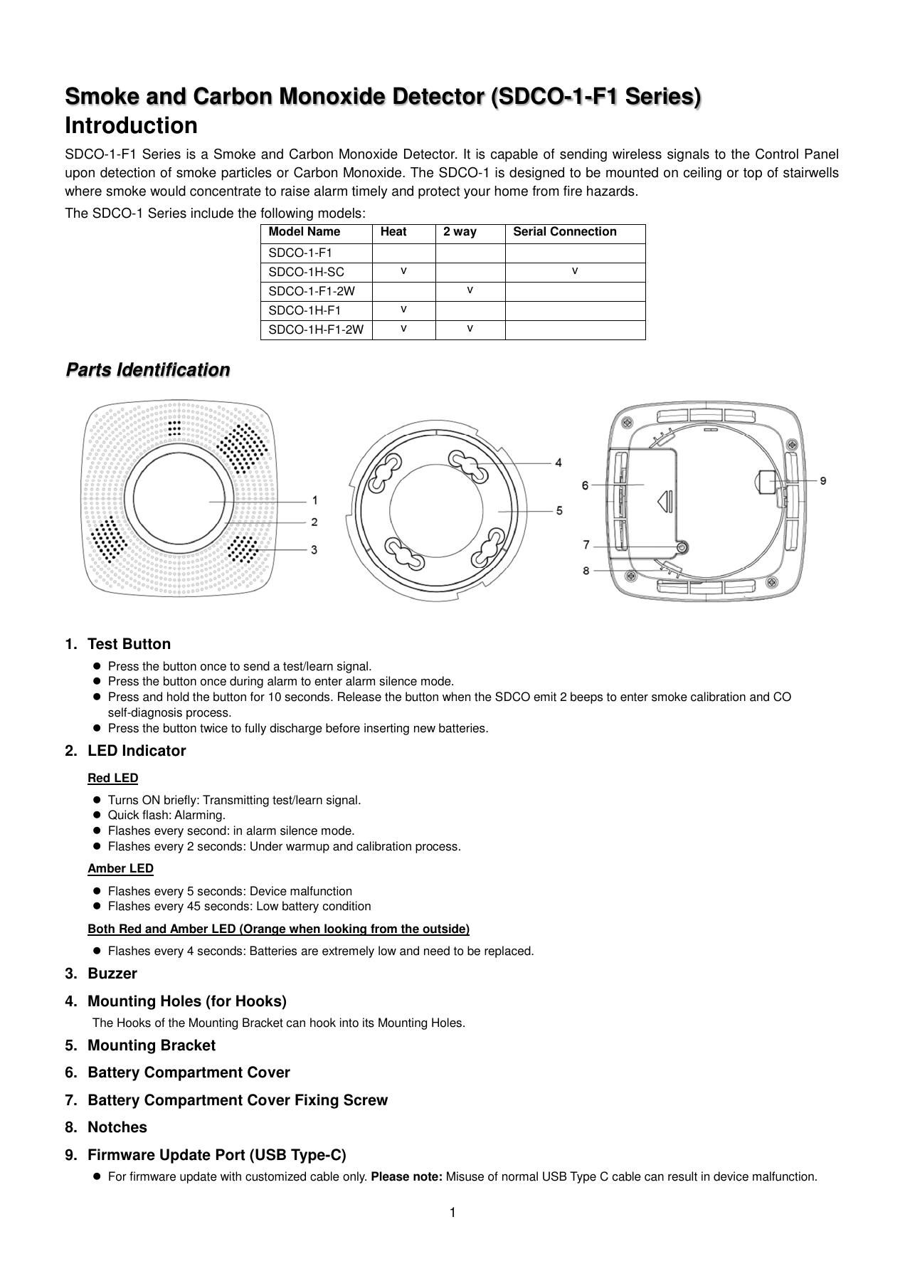
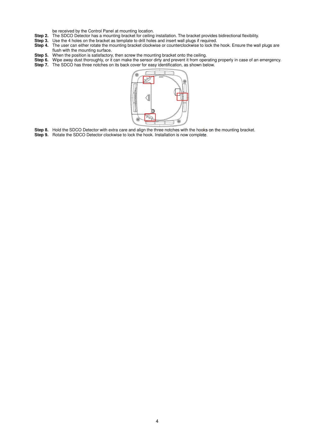
1. Take down or open
- Support the detector. It locks clockwise; normal release is in the opposite direction. This is inferred from the mounting description, not a separate removal instruction. Stop if it is locked or stuck.
- Locate battery cover (6) and screw (7) in the original drawing. Loosen the screw with a Phillips screwdriver and remove the cover.
2. Bytt batteri / lad
- Remove all three old batteries.
- Press the front test button (1 in the drawing) twice while the batteries are out. This discharges residual power before fitting new batteries.
- Insert three new EL123AP lithium batteries. Follow the positive and negative markings in the holder. Do not mix old and new batteries.
3. Put together and in place
- Secure the battery lid. Align the three marks with the bracket hooks and turn clockwise.
- Allow one minute for warm-up and 1–7 minutes for calibration. Wait for the confirmation sound and for flashing to stop.
4. Test and confirm normal operation
- Arrange a test. Press Test; the normal response is one red flash and a two-tone sound. Contact support for an abnormal response or continuous beeping.
Attach and Mount
- Leave the bracket in place during battery replacement. Do not move the smoke/CO detector to another room without assessing placement.
Check that the drawing and any variations in the original manual are consistent with the device. Sources checked 08.09.2026. The step marked as derived is not an explicit disunity instruction from the manufacturer.
Vesta utendørs PIRCAM HD-detektor
Coverage: Step by step – bracket release must be confirmed

Manual for this product
Battery/power: 4 × AA L91 lithium
1. Take down or open
- Carefully remove the camera from its mounting bracket. The manual does not detail how to release any lock; do not force it off.
- Loosen the battery-compartment retaining screw and open the lid.
2. Bytt batteri / lad
- Remove all four batteries. Press Test twice.
- Insert four new AA L91 batteries following the markings. Press Test once to send a battery-normal signal.
3. Put together and in place
- Secure the battery lid and refit the camera to the same bracket at the same angle.
4. Test and confirm normal operation
- Perform a walk test and check both signal and images. Confirm that battery and tamper faults have cleared.
Attach and Mount
- The bracket has two holes for a flat wall and four for a corner. Retain the existing fixings during battery replacement.
Original images and technical drawings
Technical drawing is not installed here yet. Open the associated original manual and control model before demounting.
Check that the drawing and any variations in the original manual are consistent with the device. Sources checked 08.09.2026. The step marked as derived is not an explicit disunity instruction from the manufacturer.
Vesta sentralenhet F1, 4G og Ethernet
Coverage: Use and checks – technician required to open

Manual for this product
Battery/power: No complete customer exchange procedure verified in this compilation
The source link below points to the exact article. Internal opening, cableling and full re-installation have not been turned into a general DIY recipe.
1. Take down or open
- Do not open or pull down the device with wires connected.
4. Test and confirm normal operation
- Read the status on the panel or app and note the exact fault message.
- Arrange a functional test and have normal communication and receipt confirmed.
Attach and Mount
- Keep the existing mount, orientation and wiring. Check externally that the device is not covered or loose.
Original images and technical drawings
Technical drawing is not installed here yet. Open the associated original manual and control model before demounting.
Check that the drawing and any variations in the original manual are consistent with the device. Sources checked 08.09.2026. The step marked as derived is not an explicit disunity instruction from the manufacturer.
Vesta V-MAX BUS og WIFI touch skjerm 7 VESTA-tastatur
Coverage: Use and checks – technician required to open

Manual for this product
Battery/power: Cabled supply; no customer exchange procedure for sensor battery
The source link below points to the exact article. Internal opening, cableling and full re-installation have not been turned into a general DIY recipe.
1. Take down or open
- Do not open or pull down the device with wires connected.
4. Test and confirm normal operation
- Read the status on the panel or app and note the exact fault message.
- Arrange a functional test and have normal communication and receipt confirmed.
Attach and Mount
- Keep the existing mount, orientation and wiring. Check externally that the device is not covered or loose.
Original images and technical drawings
Technical drawing is not installed here yet. Open the associated original manual and control model before demounting.
Check that the drawing and any variations in the original manual are consistent with the device. Sources checked 08.09.2026. The step marked as derived is not an explicit disunity instruction from the manufacturer.
V-MAX BUS power supply KIT
Coverage: Use and checks – service required for removal

Manual for this product
Battery / power: Battery battery in power supply box; service work
The source contains an expressly obsolete drawing and several model references. Battery size and connection form should not be derived from the old figure.
1. Take down or open
- Do not open the enclosure for this customer task.
4. Test and confirm normal operation
- Note power or battery faults and which BUS devices are affected.
- Arrange service using the full model designation on the enclosure.
- Confirm normal power, charging and communication after service.
Attach and Mount
- Keep the existing mounting and cables. Removal and new installation are not described as customer tasks in this guide.
Original images and technical drawings
Technical drawing is not installed here yet. Open the associated original manual and control model before demounting.
Check that the drawing and any variations in the original manual are consistent with the device. Sources checked 08.09.2026. The step marked as derived is not an explicit disunity instruction from the manufacturer.
Vesta Hybrid 4G
Coverage: Use and checks – technician required to open

Manual for this product
Battery/power: Cabled supply; no customer exchange procedure for sensor battery
The source link below points to the exact article. Internal opening, cableling and full re-installation have not been turned into a general DIY recipe.
1. Take down or open
- Do not open or pull down the device with wires connected.
4. Test and confirm normal operation
- Read the status on the panel or app and note the exact fault message.
- Arrange a functional test and have normal communication and receipt confirmed.
Attach and Mount
- Keep the existing mount, orientation and wiring. Check externally that the device is not covered or loose.
Original images and technical drawings
Technical drawing is not installed here yet. Open the associated original manual and control model before demounting.
Check that the drawing and any variations in the original manual are consistent with the device. Sources checked 08.09.2026. The step marked as derived is not an explicit disunity instruction from the manufacturer.
QALLMAX TOUCHPANEL-3
Coverage: Use and checks – service required for removal

Manual for this product
Battery/power: Internal rechargeable reserve package; spare part must be identified
Although the manual shows battery replacement, it has not identified the ordered battery package here. The panel may also have another power supply module. A general customer switch would therefore become incomplete.
1. Take down or open
- Do not open the enclosure for this customer task.
4. Test and confirm normal operation
- Check the connection to the supplied power adapter. The standard configuration uses 5 V / 3 A USB-C.
- For a persistent battery warning: identify the unit as TouchPanel-3 and arrange the correct backup pack or service.
- Confirm normal operation, notifications and alarm receipt after service.
Attach and Mount
- Keep the existing mounting and cables. Removal and new installation are not described as customer tasks in this guide.
Original images and technical drawings
Technical drawing is not installed here yet. Open the associated original manual and control model before demounting.
Check that the drawing and any variations in the original manual are consistent with the device. Sources checked 08.09.2026. The step marked as derived is not an explicit disunity instruction from the manufacturer.
AC650 dobbeltbånds WiFi USB-adapter
Coverage: Use and checks – installation details missing

Manual for this product
Battery / Power: No customer exchange procedure for battery documented
Restarting or extraction can stop cameras/alarm communication. Contract operating interruption and retrieve full model manual before demounting.
1. Take down or open
- Do not open the equipment. Keep power and network cables in their labelled ports.
4. Test and confirm normal operation
- Check whether connected devices are accessible. Note which have lost connection.
- Have the power supply and network configuration checked if faults persist. Do not factory-reset as the first action.
Attach and Mount
- Check for visible damage, loose connections and clear ventilation where relevant. Note which ports are used before any agreed relocation.
Original images and technical drawings
Technical drawing is not installed here yet. Open the associated original manual and control model before demounting.
Check that the drawing and any variations in the original manual are consistent with the device. Sources checked 08.09.2026. The step marked as derived is not an explicit disunity instruction from the manufacturer.
Vesta cloud-managed PoE switch med 4 Gigabit porter
Coverage: Use and checks – installation details missing

Manual for this product
Battery / Power: No customer exchange procedure for battery documented
Restarting or extraction can stop cameras/alarm communication. Contract operating interruption and retrieve full model manual before demounting.
1. Take down or open
- Do not open the equipment. Keep power and network cables in their labelled ports.
4. Test and confirm normal operation
- Check whether connected devices are accessible. Note which have lost connection.
- Have the power supply and network configuration checked if faults persist. Do not factory-reset as the first action.
Attach and Mount
- Check for visible damage, loose connections and clear ventilation where relevant. Note which ports are used before any agreed relocation.
Original images and technical drawings
Technical drawing is not installed here yet. Open the associated original manual and control model before demounting.
Check that the drawing and any variations in the original manual are consistent with the device. Sources checked 08.09.2026. The step marked as derived is not an explicit disunity instruction from the manufacturer.
4G LTE AC1200 utendørs Wi-Fi-ruter
Coverage: Use and checks – installation details missing

Manual for this product
Battery / Power: No customer exchange procedure for battery documented
Restarting or extraction can stop cameras/alarm communication. Contract operating interruption and retrieve full model manual before demounting.
1. Take down or open
- Do not open the equipment. Keep power and network cables in their labelled ports.
4. Test and confirm normal operation
- Check whether connected devices are accessible. Note which have lost connection.
- Have the power supply and network configuration checked if faults persist. Do not factory-reset as the first action.
Attach and Mount
- Check for visible damage, loose connections and clear ventilation where relevant. Note which ports are used before any agreed relocation.
Original images and technical drawings
Technical drawing is not installed here yet. Open the associated original manual and control model before demounting.
Check that the drawing and any variations in the original manual are consistent with the device. Sources checked 08.09.2026. The step marked as derived is not an explicit disunity instruction from the manufacturer.
Vesta cloud-managed PoE switch med 8 Gigabit porter
Coverage: Use and checks – installation details missing

Manual for this product
Battery / Power: No customer exchange procedure for battery documented
Restarting or extraction can stop cameras/alarm communication. Contract operating interruption and retrieve full model manual before demounting.
1. Take down or open
- Do not open the equipment. Keep power and network cables in their labelled ports.
4. Test and confirm normal operation
- Check whether connected devices are accessible. Note which have lost connection.
- Have the power supply and network configuration checked if faults persist. Do not factory-reset as the first action.
Attach and Mount
- Check for visible damage, loose connections and clear ventilation where relevant. Note which ports are used before any agreed relocation.
Original images and technical drawings
Technical drawing is not installed here yet. Open the associated original manual and control model before demounting.
Check that the drawing and any variations in the original manual are consistent with the device. Sources checked 08.09.2026. The step marked as derived is not an explicit disunity instruction from the manufacturer.
Vesta cloud-managed PoE switch med 16 Gigabit porter
Coverage: Use and checks – installation details missing

Manual for this product
Battery / Power: No customer exchange procedure for battery documented
Restarting or extraction can stop cameras/alarm communication. Contract operating interruption and retrieve full model manual before demounting.
1. Take down or open
- Do not open the equipment. Keep power and network cables in their labelled ports.
4. Test and confirm normal operation
- Check whether connected devices are accessible. Note which have lost connection.
- Have the power supply and network configuration checked if faults persist. Do not factory-reset as the first action.
Attach and Mount
- Check for visible damage, loose connections and clear ventilation where relevant. Note which ports are used before any agreed relocation.
Original images and technical drawings
Technical drawing is not installed here yet. Open the associated original manual and control model before demounting.
Check that the drawing and any variations in the original manual are consistent with the device. Sources checked 08.09.2026. The step marked as derived is not an explicit disunity instruction from the manufacturer.
Vesta cloud-managed PoE switch med 24 Gigabit porter
Coverage: Use and checks – installation details missing

Manual for this product
Battery / Power: No customer exchange procedure for battery documented
Restarting or extraction can stop cameras/alarm communication. Contract operating interruption and retrieve full model manual before demounting.
1. Take down or open
- Do not open the equipment. Keep power and network cables in their labelled ports.
4. Test and confirm normal operation
- Check whether connected devices are accessible. Note which have lost connection.
- Have the power supply and network configuration checked if faults persist. Do not factory-reset as the first action.
Attach and Mount
- Check for visible damage, loose connections and clear ventilation where relevant. Note which ports are used before any agreed relocation.
Original images and technical drawings
Technical drawing is not installed here yet. Open the associated original manual and control model before demounting.
Check that the drawing and any variations in the original manual are consistent with the device. Sources checked 08.09.2026. The step marked as derived is not an explicit disunity instruction from the manufacturer.