
New: sensors and troubleshooting
PowerMaster / PM10 — search PG2 sensors · IQ Panel · Ajax smoke detectors and all manualsConnectAlarm – newer manufacturer guidance
Visonic PowerMaster-10 G2
Supplier item link
A direct supplier item link has not been confirmed for this entry. A general supplier website is not an item link.
Troubleshooting – step by step
Visonic → Teletec → Sikkerhetsgruppen
Central for PowerG devices, with support for a wired zone. This is not PowerMax.
Gjelder PowerMaster-10 G2. User manual: version 19.4. Installation manual from Teletec: version 19.3. If the label does not say G2, confirm the correct manual before following these steps.
Teletic article number and purchase price: not confirmed.
Daglig bruk
Arm the alarm
- Check that the display shows READY (KLAR). For NOT READY (IKKE KLAR), use the information button to identify the zone requiring attention.
- Select AWAY (BORTE) when leaving or HOME (HJEMME) for agreed partial arming. Enter your code if requested.
- Leave within the exit delay and confirm arming.
Disarm the alarm
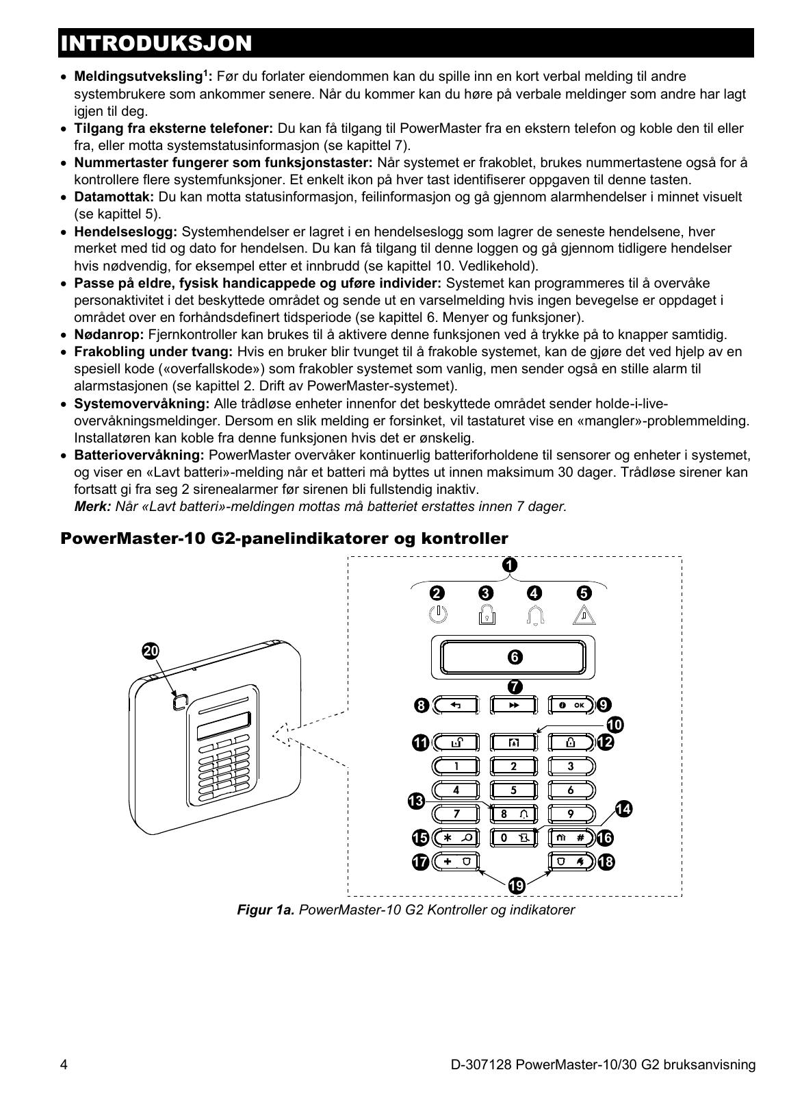
- Use the agreed entrance. Press the button with the open padlock.
- Enter your personal code or use your assigned tag where supported.
- Check that the armed indicator goes out. MEMORY (MINNE) may still show a previous alarm.
Wrong or Low Battery
Notes zone number and the whole message. CPU LAVT BATTERI applies to the central reserve battery; sensor errors must be followed up on the correct model. The user manual refers battery replacement to the installer. Do not open the central as normal customer exchange.
For ansatte
- Record panel model, software version and communicator before work.
- Use the PowerMaster-10 G2 chapter in the installation manual; PowerMaster-30 drawings are different.
- For new sensors, check PowerG variant and frequency and use the device's own manual.
- Check zone, location, signal and alarm reporting after changes. Document the result.
Teletec: PM Communicator LTE PM10/30/33 – produkt 119913
Confirm module support, software and receiver setup before ordering.
Old documentation reviews 2G/3G. Do not use this as confirmation of today's mobile coverage or module support.
PowerMaster-10 G2 – installation, from PDF page 11Documents and missing
- User guide
- Norwegian summary and full Norwegian user manual, G2 version 19.4.
- Installasjonsmanual
- English original manual from Teletec, version 19.3.
- Data sheet
- Manufacturer PowerMaster-10 Datasheet. Check order variant.
- Produsent
- Model page with manuals, photos and movies.
- Teletec
- Document link confirmed; central product link, order number and price missing.
- Sensors and Older PowerMaster-10
- Exact sensor list and manual for older non-G2 facilities missing. PowerMax or other radio devices are not automatically compatible.
Help when the product does not work
Choose the symptom and check the model scope before following the steps. This is troubleshooting, not a list of confirmed product defects.
PowerMaster shows NOT READY
Applies to: PowerMaster-10 G2. PG2 accessories only when fitted to this panel; not PowerG+ or IQ Panel.
- Read the display and review open zones/faults as described in the user guide. Record the zone, room and full message.
- For an open door or window message, close it fully. Look to see whether the magnet and sensor are still in place.
- Check the display again. Battery, tamper or communication faults require the named sensor manual. Do not replace the panel battery because of a sensor fault.
- When the panel is ready, use normal arming. Do not bypass an unknown zone or force arm to remove the warning.
Check the result: The panel shows READY with no unresolved fault and normal control works.
Stop and get help: If the zone remains open or the fault concerns communication/tamper, contact support with the zone and sensor model.